As time goes by, the successful designer will need to deal with more complicated parts (e.g., major sub-assemblies having more complicated control algorithms). I usually start that discussion by telling said designer something they’ve already figured out (if not articulated): design is often a sort of a “trial-and-error” process suggested by the archetype in Figure 21.

Here, I’ve extracted some work from step 4 (“Synthesize Detailed Design”), along with the actual decision point in order to better distinguish “work” from “decision”. Note that I’ve also moved the “decision number” into an actual “decision block”. A little bit of color-coding has been added, where the orange (-ish) tone designates things that are of particular interest to the “System Engineering” discipline.
The looping associated with trial-and-error is made explicit in Figure 2 by recognizing the assessment of design adequacy (“does THIS one work?”). The professional nomenclature for disciplined “trial-and-error” is a hypothesis-testing-and-revision process historically referred to as the “Scientific Method“. The loop provides for project-specific revision and refinement of each iteration’s hypothetically suitable design2.
The notion of a yet-to-be-tested hypothesis has critical implications for managing process complexity. Figure 3 introduces notions of formal decomposition and recursion. Decomposition allows for increasing the level of detail in the hypothetically suitable design. Recursion stipulates that the same process is applicable at that increased detail.
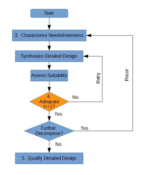
The adequacy of a hypothetically suitable decomposition3 remains “open” or “unconfirmed until the individual adequacies of its decompositions have been assessed (at least preliminarily). It is possible for multiple upper-tier candidates to be under consideration while their decompositions are under assessment. The designer must be prepared to clearly segregate information for parallel candidates and, within each candidate, each candidate decomposition.
The notion of determining which of several candidate designs (including their decompositions) is preferred is usually referred to as a “Trade Study“. I usually defer discussion of that subject until after this one. I find that the discipline required for an objective Trade Study is better taught if the discipline for managing the data is already in hand.
The notions of complexity and recursion are exactly analogous to those encountered in recursive programming, except that the designer must hold parallel universes “in memory” at the same time. We create a network of memory “stacks” to preserve decisions held in abeyance pending the work conducted at the next more-detailed level. If we run out of memory address space, or lose track of where we’ve posted that level’s data and status, we’re in a lot of trouble!
My conversation with the designer quickly diverges from even this augmented flow. I don’t want Figures 2 and 3 to be taken literally and to the exclusion of all other conceptual processes, but I need to use them as a bridge from the archetype (used for all-custom design) to variations on the theme. Although the concepts introduced by these two figures are crucial, I don’t like to let them dwell long enough to seem as if the exact details of these flow charts are somehow a “default” process.
Process A: Standard Parts
By the time we have this discussion, the Design Engineer has typically been exposed to the concept of Standard Parts. That concept exists in order to avoid re-inventing the wheel. Figure 4 illustrates the basic concept, which matches the as-specified characteristics of a parts as found in a catalog to the need (or intent) of the design.
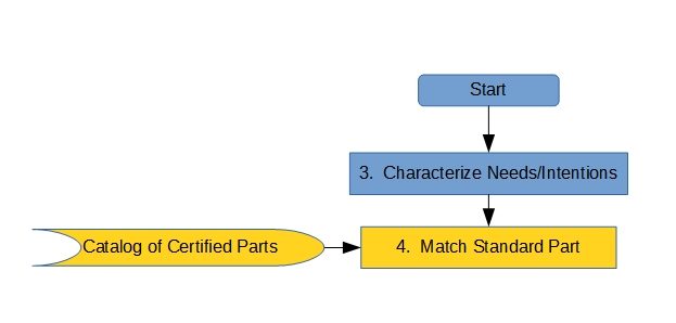
Note that a critical distinction is made here between the concept of “standard part” and “commercial part”. A standard part is manufactured in response to a specification (often in sheet form) that exists for no specific End Use, and has been formally qualified to meet its allocated requirements for performance and physical characteristics. A commercial part is developed on speculation of sale (often to the general public with minimal restrictions) and rarely has any allocated requirements. It typically has no formal qualification data on which our End User can rely.
Because it has already been formally qualified, a standard part needs no additional (dedicated) qualification4; its use does, however, entail formally verifying that its Next Higher Assembly uses it within the limits of its qualification data. Examples of standard parts include fasteners, connectors (e.g., electrical, pneumatic, hydraulic), mechanical power transmission components (gears, screws, etc.), lubrication, and cables.
Most non-SE’s understand the immediately proceeding paragraph, but I find that many SE’s fail to understand its implications. SE’s will often try to cover the situation with something akin to Figure 1, as if requirements are being allocated to the standard part, necessitating qualification. In reality, requirements are being allocated “up the tree”, to ensure that the standard part’s “next higher assembly” imposes loads on the part that are within that part’s capability. Failure to comply might, or might not, cause selection of a different standard part, but the direction of allocation remains upward as long as a non-custom design is desired.
Note that the catalog5 contains significant information about how the part characteristics are parameterized6. Knowledge of this information, typically acquired as the result of (sometimes bitter) experience by the Engineering staff, feeds the provisional characterization of need/intent. This relationship, which is really a data abstraction meta-step, is not shown in Figure 4, but is critically important to the long-term efficiency of the design process and to the designer’s maturation.
The above paragraph is very important in the grand scheme of things. To clearly articulate my intent: a good designer uses their experience to minimize new design efforts, thereby saving time, money, and developmental risk. They might even compromise a bit on performance in order to do so. A greedy designer wants to do everything from a clean sheet, writing new requirements whenever they can.7
A good System Engineer helps the good designer and tries to contain the bad one. A bad System Engineer does the opposite. That’s one of the most important ways you can tell the difference between the good and the bad8.
As with other processes here, Figure 4’s flow is equally applicable to algorithm development, except that the “catalog” might not always be as formal as it is for hardware9.
Process B: Re-use of Existing Dedicated Parts
Figure 5 tweaks the idea shown in Figure 4, the difference between these two variations being the existence of formal qualification data that are specific to the original developmental requirements for the part being reused. This pattern usually involves a previous in-house development effort, but can also occur when re-using some part previously developed for the “current” customer (that is, the current customer owns the Intellectual Property, so can readily approve the item’s use toward the new purpose).
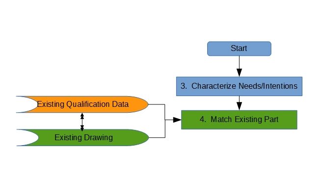
The process shown in Figure 5 can degenerate10 further, if the developmental customer directs the developer to use some specific existing design for part of the current project, which effectively eliminates any decisions with regard to the characteristics of the directed part. This case is shown in Figure 6: it will be noted that there are actually no decisions in-scope to this variation. Engineering of the next-higher assembly is, of course, required to accommodate the characteristics of the directed design solution, no matter what they are. The associated risk is tacitly assumed by that customer, and the developer must ensure that the contract so stipulates.
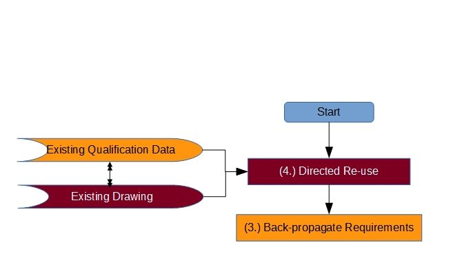
“Back-propagation of Requirements” means that the developer creates a set of data representing the characteristics of the directed design as if it had been developed from scratch. That ersatz requirement set is then collated with the other requirements to show completeness of the set with respect to the upper-tier requirements. This is useful when creating a functional model of the as-required capability, but otherwise has little influence on the system’s development. Because these “requirements” are not real, they must be clearly designated in any requirements data set; failure to do so makes it look as if SE is trying to write requirements for stuff that already exists11.
It might be supposed that Figure 6 should look just like Figure 5, and that no requirements should be back-propagated. The primary distinction between the two situations is that dedicated qualification data exist in the second case (Figure 6). The developer will wish to contractually cover their usage of the (directed) part by explicitly tracing to the known requirements and qualification data, further limiting their legal exposure if the directed use turns out badly.
The notion shown in Figure 6 admits to the possibility of the project’s producer building the directed design “to print”. The directed use case can itself be extended to include furnishing of the physical part itself during manufacturing, and can be subtly varied to include “existing” designs that are not actually complete yet. This condition is referred to as “Furnished Equipment” (FE), and impacts subsequent manufacturing planning processes in a similar manner.
The directed cases are often used by a customer where a particular standardized interface is desired (e.g., to facilitate interoperability), or where substantial time and funding have already been invested in particular functionality or robustness with respect to environmental conditions. In all cases, that decision is the prerogative of the developmental customer. After all, it is their nickel.
Process C: The Use of Interchangeable Commercial Parts
The discussion of standard parts differentiated them from commercial parts as clearly as possible. Figure 7 speaks to those parts (commercial) with regard to how they can be incorporated into non-commercial systems. The most important deviation from standard parts is that commercially developed designs rarely (if ever) carry certified data with respect to their capability. The figure suggests that certification data for this purpose should be obtained when the parts are first procured. The practice will often add considerable expense to the commercially quoted price, which is often disregarded during the proposal phase (to everyone’s eventual chagrin).
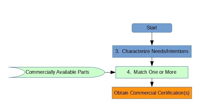
This type of design is often implemented by means of a Vendor Item Control Drawing (VICD), which controls which specific vendor Part Numbers are used in the next-higher assembly. That usage is designated by an Administrative Control Number in lieu of a true part number12. It is possible to designate more than one vendor part number for this substitution; that substitution is bookkept in the VICD13.
The designer and SE are cautioned here that the “unintended functionality” may vary from one vendor’s version of the item to another’s, especially those resulting from field upgrades to firmware after the system is fielded. Certain risks are therefore inherent in this practice. This is particularly true when a vendor retains a model number, but rolls a Part Number. For that reason, model numbers do NOT indicate interchangeability, and should never be used in a VICD.
It should be noted that some commercial suppliers don’t meet even the minimal industry standards for identification (part number designation). Such items can still be incorporated into the design using an Identification Cross-Reference Drawing (ICRD) instead of a VICD. Unlike a VICD, if the item is described carefully enough, an ICRD can be used to procure and accept items using the model number with only moderate risk.
Process D: Extension of Qualification Data to Verify the Use of Existing Parts
Sometimes we can identify a part that is known to be almost good enough for the purpose at hand, and we’re willing to pay for an extension of knowledge about that part’s capability without re-designing it14(Figure 8). This is achieved in different ways, depending on who pays for the “extension” and who does the work.
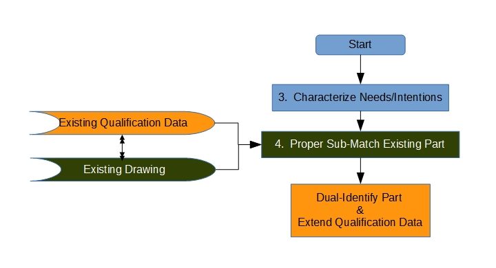
If the using developer (“us”) extends the data, then it owns the Intellectual Property with regard to the new data. We’d typically use an ASME Source Control Drawing (SCD) to denote that association, with both the design-to and verify-to requirements recorded therein (an SCD looks a lot like a specification, but it drives verification only, not design). In some cases, it might be necessary to “back propagate” ersatz requirements as discussed above.
Of course, if the supplier does the work and pays for it, then the supplier can, under their own internal Configuration Control, either apply the new data to the old part or use a new part number (even if the design is physically identical). In that case Figure 8 doesn’t apply: in effect, we retroactively apply Figure 5 as if that’s what we were doing all along15.
Process E: Restriction of Qualified Characteristics (Screening) for the Use of Existing Parts
Figure 9 represents sort of a logical inversion of Figure 8: the case where an existing part is allowed a wider range of tolerance that our present project can stand, but is otherwise suitable for our intended use. Selection can be on the basis of performance, intended function, unintended function, physical characteristic, or any combination thereof. Iff the qualified variation is conclusively relatable to some combination of acceptance criteria, then we can “up screen” those parts as they come off the supplier’s production line. This can be a dicey and expensive proposition, but is sometimes the most cost- and/or schedule-effective way to develop a product. This process is usually implemented with a Selected Item Drawing. With subtle tweaking of Figure 9, the approach can also apply to Standard Parts and Commercial Parts.
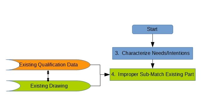
This is essentially the way that many processing units (chips) are differentiated into performance levels. They’re all made on the same line, but some turn out to be faster or have more usable cache than others. The less capable units are cheaper (but still profitable). They allow the supplier to sell “crippled” units (that must otherwise be scrapped) as if done on purpose.
In most cases, it will be far more cost effective for screening to be executed by the OEM. Any other screening source will be charged at least a re-stocking fee for those items that do not pass the screen.
Process F: Alteration of Existing Parts
Figure 10 addresses the case where most characteristics of an existing part meet the needs and intention of our overall design, but we need to tweak the part’s design a bit. “Tweakage” can be simple (re-paint a housing) or complex (re-write and load new firmware, or change a gear in the transmission); it can be either permanent (drill new holes) or reversible (remove a hard-mounted lens cap that came installed on a camera). It can be applied to existing qualified parts being re-used, to Commercial Parts (not explicit in Figure 10) or to Standard Parts (also not explicit in Figure 10).
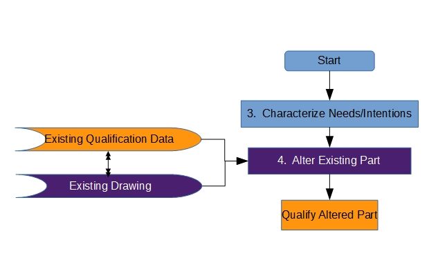
Re-qualification, which may or may not be trivial, is necessary to extend qualification data from the original part number to the new part number as assigned to the altered part. Qualification is usually by Analysis, with Similarity being used to address the previously qualified characteristics of the part16. It is necessary to pay at least cursory attention to the impact of the modification on each such characteristic. The alterations themselves are typically qualified with respect to new17 requirements by any of the classical methods.
←Back to Part I: Introductory Discussion
On to Part III: Advanced Discussion→
Footnotes- Figures are numbered consecutively throughout the entire CI Development Cycle series of pages.[↩]
- The design itself is actual, even if not yet completed in detail. It is the suitability which is only a hypothesis until block 5 is complete.[↩]
- Which is an aspect of the design that’s being decomposed. [↩]
- Those data are embedded in, or pointed to by, the catalog, so are not explicitly shown here.[↩]
- more of a list-of-lists, really, that might be unique to the developer’s employer, customer, or industry.[↩]
- that is, what their formal measures are[↩]
- This philosophical distinction extends to the subsequent sections of this discussion.[↩]
- It turns out that “ugly” isn’t an important issue. But I like the music.[↩]
- Dr.’s Knuth, Press, Teukolsky, et al might well disagree with this conjecture. If so, I would not presume to argue with them![↩]
- …and I use that word with malice afore-thought…it can get crude.[↩]
- Which makes all the other Engineers snicker at us. Just because they’re smug doesn’t mean they’re wrong![↩]
- The concept is perfectly applicable to software, but I’ve never seen it used that way.[↩]
- A more abstract approach to developing a VICD is discussed under Envelope Drawing Development, Commonality, and Redevelopment.[↩]
- The data show that the capabilities and circumstance under which they obtain constitute a “proper subset” of the multi-dimensional region we really need.[↩]
- We don’t care HOW we got to the final state of the qualification data package…we only care what that state IS when we sell off to our acquisition customer.[↩]
- The similarity parameter is “identity”, existing within some specific manufacturer’s “part number space”.[↩]
- new to the pre-alteration part, anyway[↩]