Introduction
This example addresses the situation in which a Unit Under Test (UUT) fails to exhibit the expected functionality. The core issue at hand is to characterize what the UUT actually does exhibit and, by extension of the basic concepts of functionality, the circumstances that correlate to differences of exhibition.
From an expository perspective, this example exists mostly to show how inclusion of the circumstances (conditions) on an FFBD is, sometimes, necessary in order to clearly describe the functions possessed by (or required from) a design. Although presented in a technical context, many other details of the subject situation have been abstracted or suppressed.
My Standard Caution About Examples applies to this page.
Test Setup Overview
The UUT in question was the spring-loaded, rotating, actuated four-bar linkage shown in Figure 1. A side-view of the stroke (starting from contact with the capture fitting) is shown in Figure 2. Operating in sets of four (under nominal circumstances), the mechanism effects a “capture” event on orbit throughout a wide range of initial conditions (and other circumstances), so the actual stroke depends on the actual position and orientation of the incoming payload.
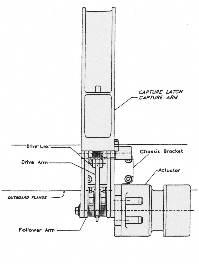
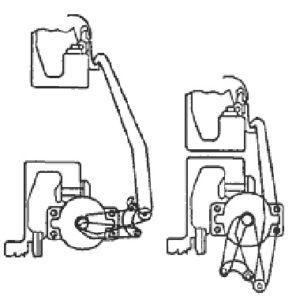
When operating nominally, the spring forces the “follower arm” to stay in contact with the “outboard flange” until the “capture arm” makes solid contact with the “capture fitting” (or anything else, for that matter!). Once such contact generates enough torque to overcome the spring, the follower arm breaks away from the flange and rotates until the capture arm is fully retracted. An internal switch is closed by that retraction, notifying the actuator controller that the stroke is complete.
Here’s an animation of a nominal stroke:
Original video credit: Boeing/NAS 15-10000
For test purposes, the UUT was inverted during Development, Qualification and Acceptance1. Figure 3 shows the UUT as installed and instrumented.
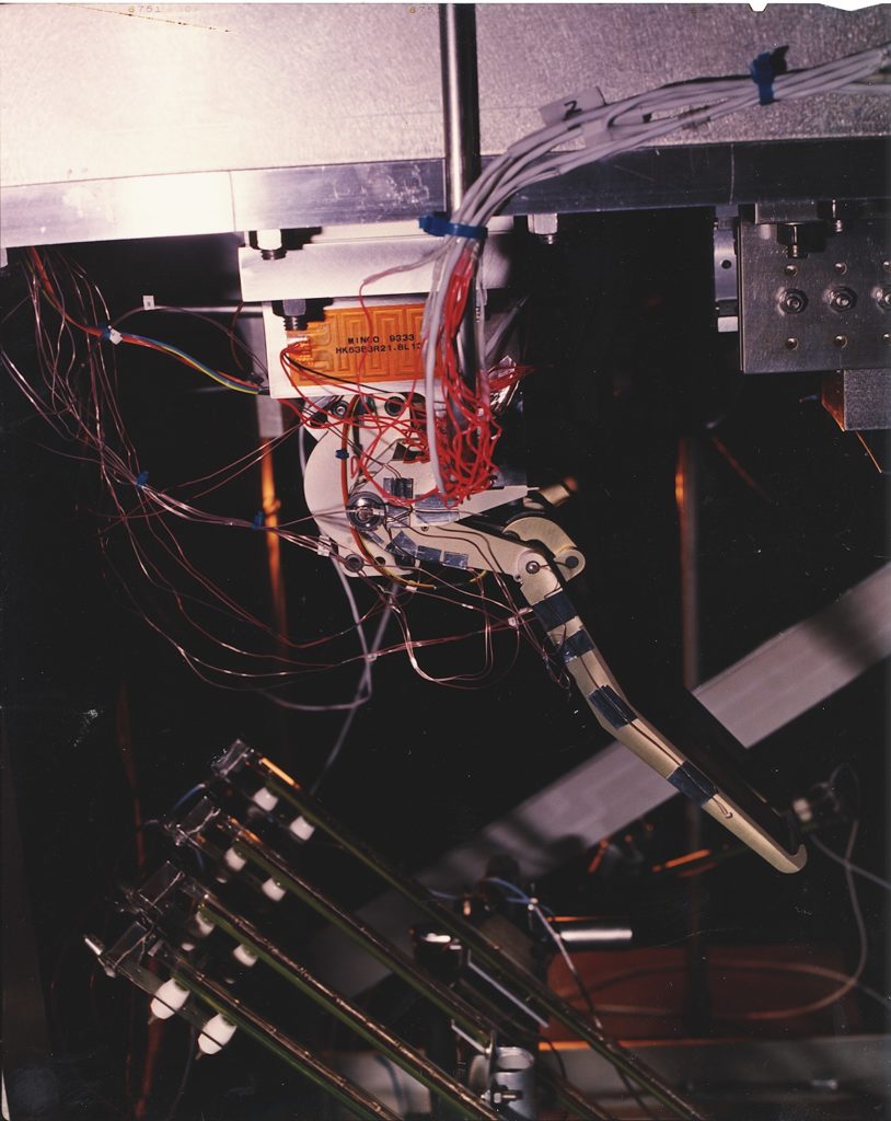
Ancillary test equipment is also notable in the setup. Of particular interest to the subsequent anomaly are the large block at the base of the latch in Figure 3 and the bank of lighting underneath the UUT. Strip heaters are visible on the block, which is also cryogenically cooled. Together with the cryo-cooled walls of the vacuum chamber itself, the UUT could be driven cold, hot, and to significant thermal gradients in both directions. Some of the thermocouple installations can also be seen on the foreground side of the UUT.
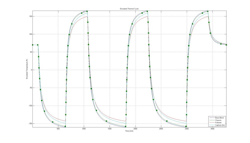
An approximating emulation of the nominal thermal cycle is shown in Figure 4. Actuation test points are shown in the figure as “filled” squares. Note that all thermal cycle in this examples are “emulated” “approximate”, generated solely for the purpose of exposition.
Aside
The extent of the thermal control devices present in the test setup may seem excessive to the unpracticed eye2. However, previous experience had made clear that two issues dominate the reliability of spacecraft mechanisms: cleanliness, and temperature. Both interfere with the control of contact loads between the internal faying surfaces, interacting to an extent not typically seen in non-space environments.
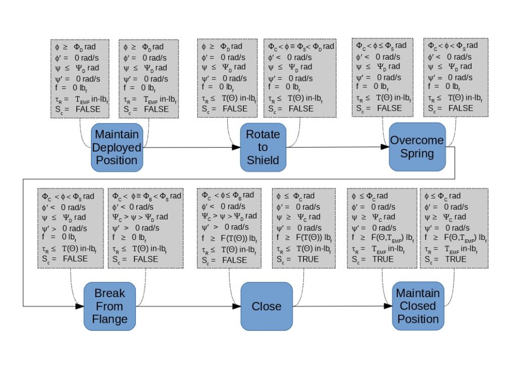
During nominal actuation in the test setup, the capture arm rotates into contact with the fitting – a counter-clockwise motion from the vantage of the cameras in these photos. The fitting (which, although flight-like, is considered part of the fixture for these tests) is mounted on a weighted slider to apply load to the latch throughout the stroke. A Functional Flow Block Diagram (FFBD) of the nominal test stroke is shown in Figure 53.
Where:
φ is the angle of the Capture Arm (in a rotating, translating reference frame), having value names as follows:
ΦD at full “ready to capture” deployment
ΦS when the latch contacts the fitting shield4
ΦC when the latch is closed5
φ’ is the derivative of φ with respect to time.
ψ is the angle of the Follower Arm, having value names as follows:
ΨD at full “ready to capture” deployment
ΨC at “capture complete”
ψ’ is the derivative of ψ with respect to time
f is the force exerted by the latch on the capture fitting
τR is torque applied by the latch actuator in the retraction (“capture”) direction, having value names as follows:
ΤEMF is the Electro-Motive Force torque required to backdrive the latch actuator when it is not energized
Τ(Θ) is the not-to-exceed actuator torque, which is a function of the drive arm angle
Sc is the state of the “capture complete” switch, which is a part of the UUT.
An example of a successful actuation during Qualification testing is shown below.
Original graphics credit: Boeing/NAS 15-10000
Aside
The stroke in the test setup is uniquely constrained. As noted above, during any given operation on orbit the fitting might be anywhere in the single-latch capture envelope upon actuation. Therefore, the load on the latch mechanism can be different on each cycle. This setup (on the other hand) results in the same load every time the latch is operated. For life cycle purposes, this is conservative because it concentrates the wear between the mechanism’s faying surfaces to a far greater extent than would operationally occur.
The unique constraint and non-flight-like drag of the instrumentation harness are literal examples of what we mean when we say that a test is “intrusive” with regard to the UUT. Other examples of “intrusion” (such as the simulation of thermal conditions) are more abstract. Any one of them alone would have been enough to distinguish this as a test instead of a demonstration. In all three cases, we had to be able to explain how the impact differed from the analogue in real flight operation. In general, it was sufficient to show that the test was “conservative”, resulting in higher loads than would really be experienced.
The ability of the latch to reach and engage the fitting in other positions was formally verified by kinematic analysis. The analysis was less formally substantiated by thousands of actuations during Development test in a Stewart (6-Dof) Platform, and formally verified at the next-higher assembly by thousands of actuations during Qualification test under thermal-vacuum conditions in an inverted Stewart Platform. Both of the Stewart Platform test series exercised the machine (and, therefore, the latch mechanisms) through a comprehensive range of initial conditions and loading patterns.
The “nominal stroke” FFBD of Figure 5 is also unique to the test setup. The flight FFBD is more complex. In particular, the flight FFBD defines how the latch behaves under dynamic, non-monotonic loading.
Test Anomaly
Not all of the actuations were successful during the Qualification test series6:
Original graphics credit: Boeing/NAS 15-10000
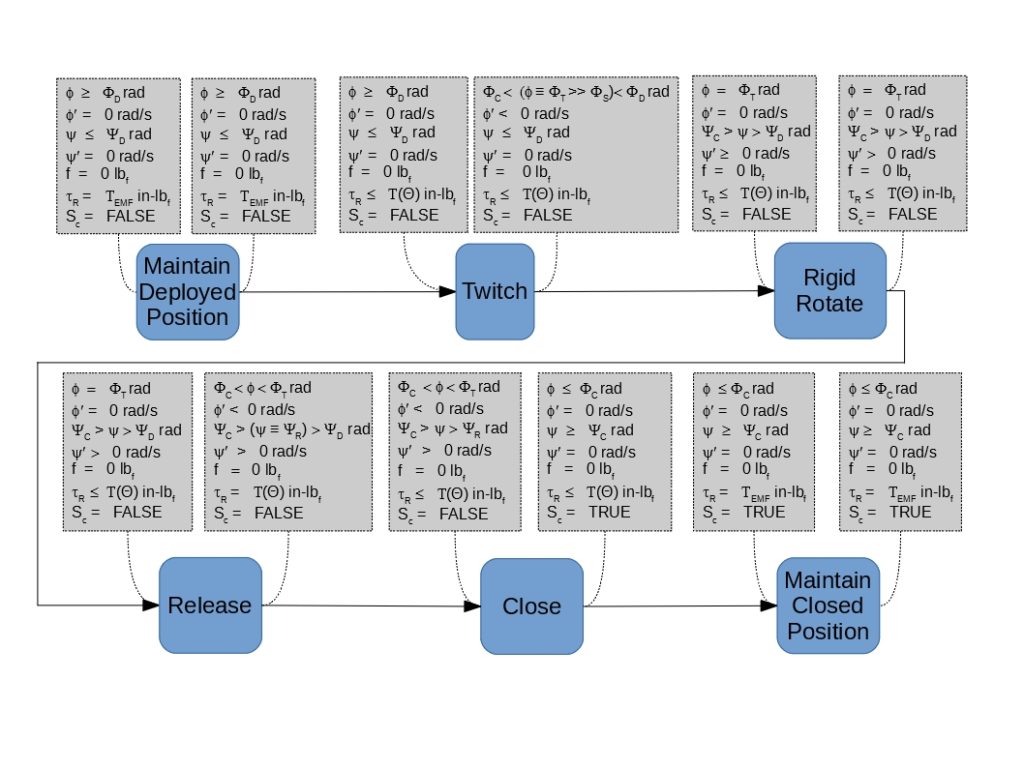
By inspection, we can depart from the nominal stroke’s FFBD (Figure 5) to describe the latch’s (mal)functionality in Figure 6.
Where, in addition to the notation used in Figure 5, the following are introduced:
ΦT is the angle of the capture arm at the end of the anomalous “twitch” in the correct direction (toward the fitting shield)
ΨR is the follower arm angle when the four-bar linkage “releases” from whatever was jamming it
As it happened, all such malfunctions occurred during cold phases of the thermal cycle, and all of them occurred after several successful actuations at warmer temperatures, there having been no intervening disturbance of the setup. Furthermore, successful strokes were also conducted at warmer temperatures after the first observation of the anomaly. During those subsequent strokes, no evidence of the anomaly was observed.
Resolution
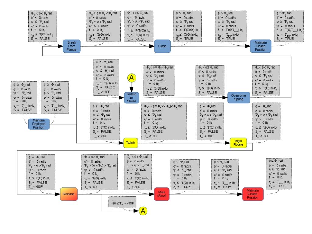
On the basis of prior and preliminary strokes as discussed above, the troubleshooting team summarily discarded all theories other than those that involved thermally-induced phenomena. Such phenomena include, but are not limited to, reduction of clearance, gradient-induced distortion, increases in stiffness, and changes in coefficient of friction. In effect, formal troubleshooting began with the unified FFBD shown in Figure 77.
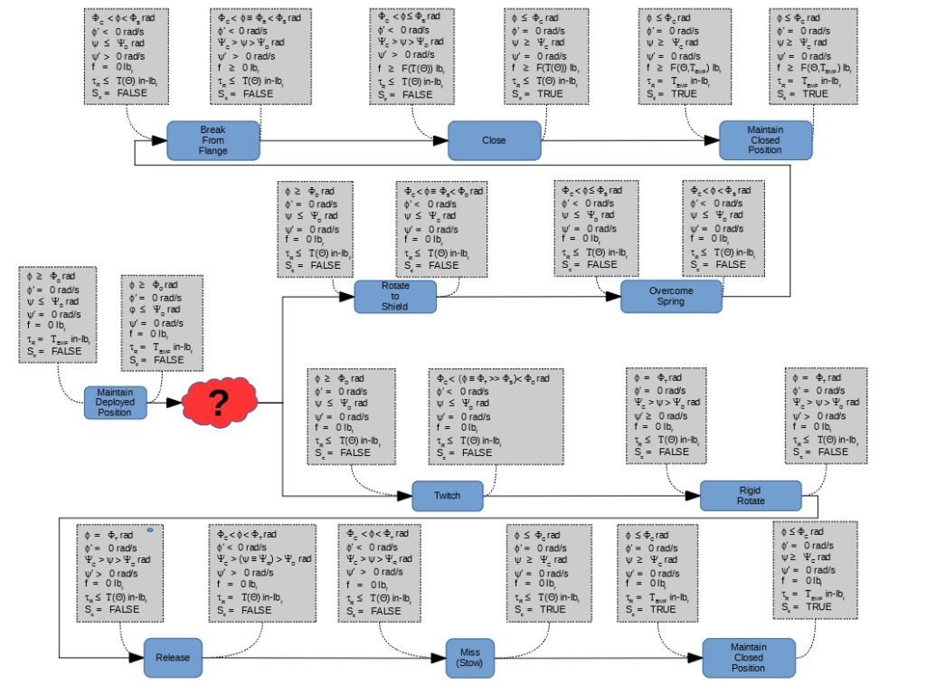
Although it was clear from the outset that (cold) temperature was the discriminating factor between the two major branches shown in Figure 7, the extent of the anomaly was not directly evident from the early data.
Furthermore, the rigid rotation strongly indicated that the degree of freedom normally afforded by the four-bar linkage was being restricted during the anomaly. That is, one (or more) of the joints in that linkage were “locked”, being itself overwhelmed as the internal loads changed during the frozen stroke. No indication of which joint, however, was available in the existing data, and no non-destructive method was available to directly resolve the issue.
Anecdotal data were made available early in the resolution to the effect that certain issues had arisen during instrumentation of the UUT: cement used to attach some of the sensors had “escaped”, running towards one of the joints. Since disassembly of the latch might well disturb any residue that might be in that joint, we were highly motivated to obtain data conclusively establishing a high correlation between that joint’s temperature and the incidence of the anomaly.
Drawing the Reader’s attention back to the thermal provisions in the test setup (discussed above), the Test Conduct Team was able to manually operate those provision in non-standard manner to adjust the internal thermal profile of the UUT. Figure 8 illustrates the type of cycle profiles exercised during resolution of the anomaly. Figure 9 samples the variability of the internal thermal profiles resulting from the cycle profiles in Figure 8.
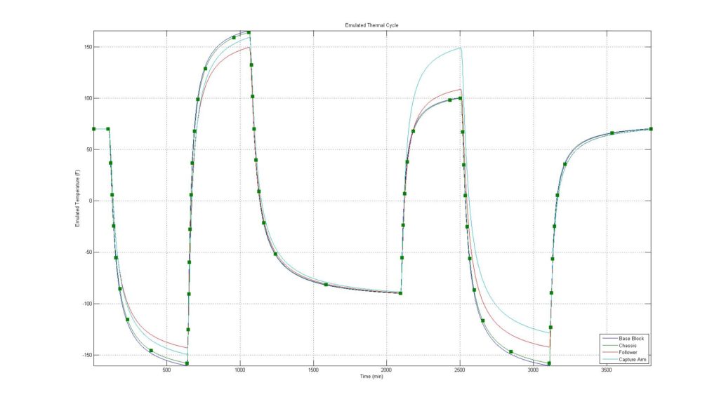
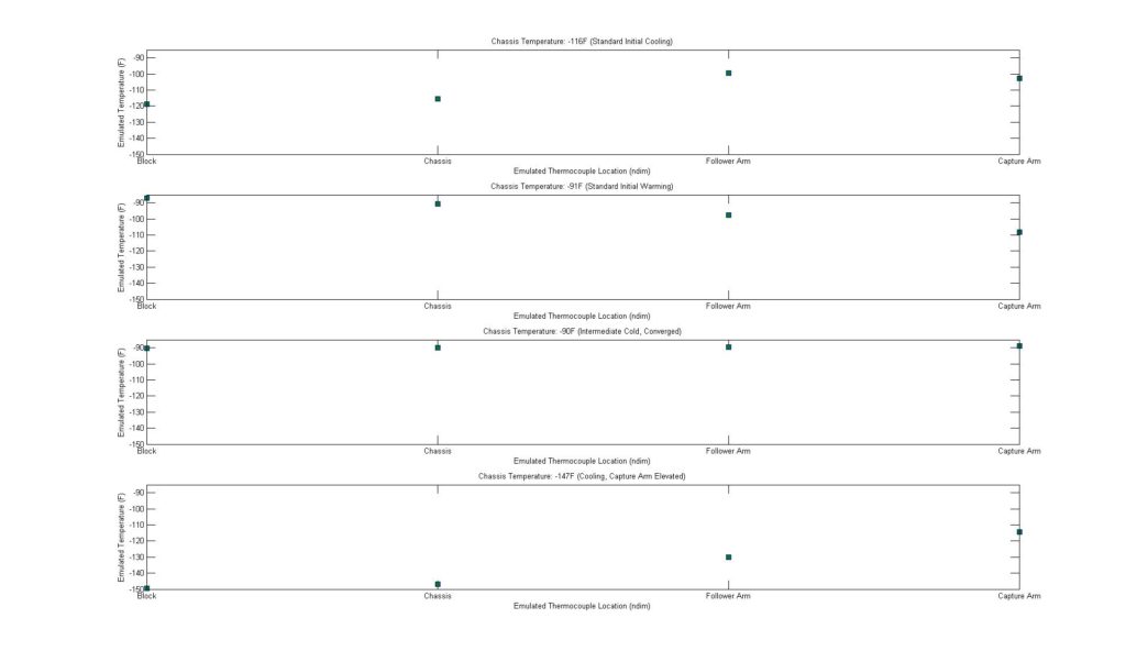
Such profiles allowed the Test Conduct Team to “drift” the latch mechanism through different combinations of joint temperatures, establishing a reliable correlation with the joint suspected of cement contamination, leading to the unified FFBD shown in Figure 10. The unified diagram illustrates the inclusion of functionally discriminating conditions (circumstances) such as might be necessary to expose branching in an overall FFBD (in this case, in a descriptive usage).
Aftermath
Subsequent to the experimental troubleshooting described above, the subject UUT was removed from the setup and disassembled. Anomalous particulates were observed being created at the suspect joint during disassembly, with residue present in that joint after disassembly was complete. As a result, the anomaly was formally dispositioned as unique to that setup, and no design changes were required.
Once the design was exonerated, all interest in the unified FFBD was lost, and the old viewgraph was discarded with the rest of that month’s trash.
Footnotes- While aggressive in comparison to actual operation in a gravity-free environment, the inverted position ensured significant actuation margin while avoiding the complexity that would accompany any off-loading the weight of the UUT.[↩]
- As they did to some of the management at the time![↩]
- As with all the FFBD’s in this example, Figure 5 was reconstructed from memory, first principles of the subject mechanism, and observation of the included diagrams and videos.[↩]
- which depends on where the fitting is in the capture envelope[↩]
- i.e., “Capture complete”[↩]
- The stroke shown here was not actually the first oddity noted with the particular UUT: the first observed anomaly “released” soon enough in the stroke that it still captured the fitting.[↩]
- No such documentation was formally produced. A similar figure did, however, briefly exist on the back of an old viewgraph.[↩]