Introduction
My Standard Caution About Examples applies to this page.
The purpose of this example is to demonstrate useful aspects of the Functional Flow Block Diagram which, as noted in the link, I use as a tool to bootstrap development of a certain class of system characteristics. Because the example contains elements of both synthesis and analysis, there are several branches that could have been taken, but weren’t. Some of those branches generated figures that are unique to their excursions. Although I’ve tried to be clear with respect to that issue, the reader is forewarned to pay close attention to it.
This page makes liberal use of “asides” to address those roads not taken, along with other types of observations. Footnotes are also used to make ancillary points but, as always, can be ignored on the first read.
Start with ad hoc input: suppose we desire to produce air (as if for some arbitrary downstream process) that is “pressurized”. We proceed “as if for the first time” in the sense of a newly minted System Engineer1.
Context Level
The classic FFBD block would be similar to Figure 1(a). Following the basic concepts described in Topical Parameterization leads immediately to Figure 1(b), which is explicit about the parameter we already know is to be controlled. Because it directly measures how well the function is performed, pressure rise is a Measure of Performance (MoP).

We proceed directly to dealing with the ranges of pressure that are relevant to the use of compressed air. Issues about the range of the admitting parameters have to consider not only upstream processes (if any), but the conditions that obtain during operation. Value ranges of the consequential parameters depend on the characteristics of downstream usage, but can be heavily influenced by an intent to induce conditions that provide (or contribute to) the environments in which downstream processes execute2. These two issues initiate the legacy concept of “System Integration”, in which the System Engineer starts to characterize the relationships between various features of the system, which is the core definition of “analysis”3. Figure 1(c) illustrates the appearance of the FFBD once this obvious issue is resolved4.
We apply a basic knowledge of physics and thermodynamics5, this being the “engineering” part of “System Engineering”. In this case, we know that “air” is a compound material characterized by more than just pressure, and that there are relationships between pressure and the other primary parameters typically used to describe air (volume, temperature). At least two theoretical concepts of compressing gasses exist: that it can be conceived of as adiabatic (without the interchange of heat) or as isothermal (without a change of temperature).
In an adiabatic process, neither heat nor materiel crosses the boundary of the component(s) performing the compression. Energy is added to (or removed from) the component only in the form of “work” (force acting through a distance). The temperature of adiabatically compressed air doesn’t remain constant. The governing equation is
In an isothermal process, the temperature does remain constant, and non-work energy can enter or leave the components executing the function. Isothermal compression of the air is governed by
where the difference from adiabatic compression is obvious from comparison of the two equations.
Aside
The equations shown here are, of course, mere approximations that rely on a host of idealized6 assumptions and simplifications. In reality, the compression will be neither adiabatic nor isothermal, but somewhere in their general vicinity. We can (and should) examine both concepts as part of analyzing the subject function. Selection of one in preference to the other will depend on how the compressor is integrated into the system. Thermal characteristics of the integration will, of course, be very important to that selection.
Secondary research7 also identifies the composition of normal air as mostly nitrogen, with some oxygen and other trace elements, and some water vapor. The concept of partial pressure should also surface, along with those of “humidity”, “dew point”, and “mixing ratio”8.
These pieces of information, together with the equations, generate additional questions: e.g, “what temperature ranges are acceptable?” and “what range of dew point is acceptable?”. It will turn out that the answers depend entirely on the use to which the compressed air will be put. I would (therefore) expect an intermediate posture as seen in Figure 2 while those questions are identified and resolved9.

As shown, Figure 2 would probably never exist in published form: it is as if scrawled on the whiteboard as the System Engineer thinks things through. Important Integration issues yet remain to be resolved: we have not yet established whether the subject function will, in fact, be responsible for (1) providing (or rejecting) heat energy to manage the temperature and (2) providing for (or disposing of) water to manage the dew point10. In many projects, it is not unusual for there to be centralized management of both properties. The System Engineer should actively participate in assessment of the potential for common functionality to resolve both issues.
Aside
Note that Figure 1(c) is agnostic with respect to parameters like final temperature. Any of the three subfigures in Figure 1 can, therefore, be used to “kick the can down the road” and force issues of physics to be dealt with later. Since the physics are clear at this early point in the process, there is no technical reason to do so. “Kicking the can down the road” is never my preferred course of action if any reasonable alternative is known to exist.
Figure 3 represents an evolution of understanding from Figure 2 as the aforementioned equations are executed in the proposed operational context. Of particular interest is the formulation of numeric values for the controlled parameters, which warrants some focused attention: Figure 3(a) implies that Temperature and Dew Point can be independent11.
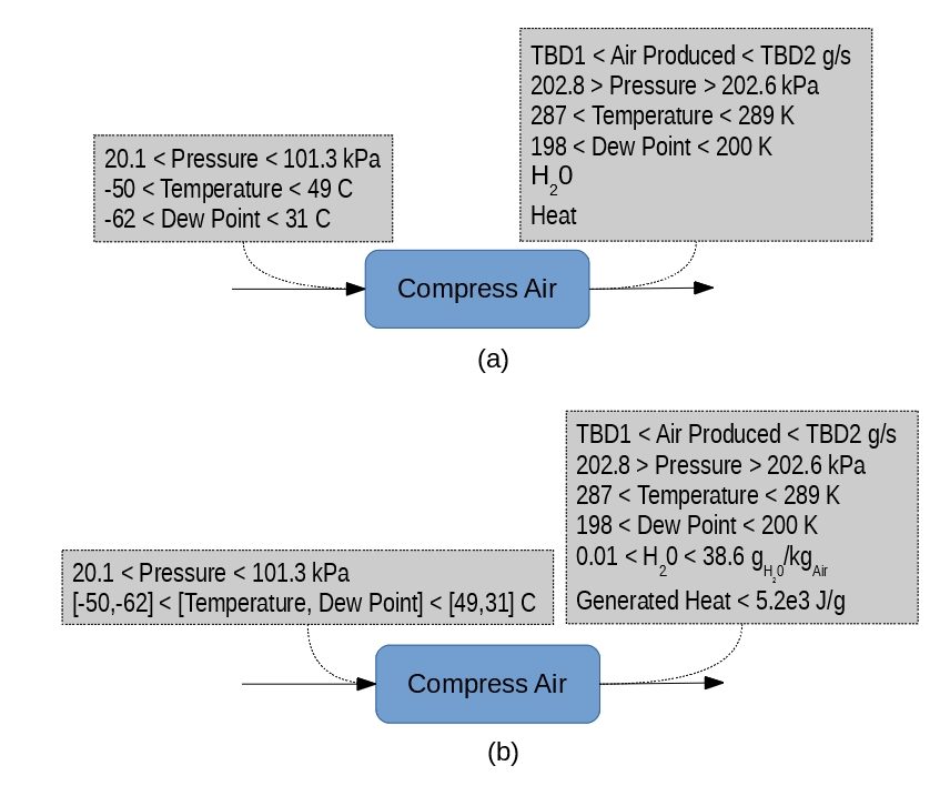
Although the format of Figure 3(a) would directly support writing performance requirements12, it will inevitably lead to the concept of verifying performance of the design at all four “corner” points, including the [-50,+31] pair13. A more reasonable formulation of these values is shown in Figure 3(b), where Temperature and Dew Point are treated as being vector-valued. Here, the water produced during compression and the heat produced (or consumed) by the process are both estimated as an adiabatic process, given pre-compression conditions adapted from MIL-HDBK-310 and NOAA 14.
Water and generated heat are managed by the subject function only in the sense that they’re consequences of that function’s physics. Both parameters require additional management by other functions in the system. The practice we’re using here identifies them as such15, and provides initial sizing relationships.
Both water and heat have been left as “extensive” properties for which intensive values can be calculated from the rate of compressed air production. This is by intent: some of the designs that are capable of meeting requirements that might be derived from this Analysis will intentionally over-compress and then relieve down to the target pressure, and they might produce more heat and water than are quantified here. Quotation of estimates in extensive form serves as a clear reminder to subsequent horizontal integration of such design approaches. It also decouples this analysis from the details of system sizing, which will often be conducted in parallel during development of complex projects.
Aside
Figure 3 shows the flow of produced air as if it is a constant value. Consumption rates are (however) rarely constant. In this case, it would almost certainly be necessary to treat consumption as a rate averaged over time along with a peak value, generating multiple Measures of Performance for a single function. It may also be necessary to specify a “duty cycle” in order to handle heat. None of those concepts are shown, because they don’t add to exposition of the basic concepts of interest here.
Figure 4 shows what happens when we further combined pressure into a triplet with Temperature and Dew Point16. With this additional relationship, the maximum theoretical heat generated by the process is reduced by more than a factor of three. Such a triplet would still be an MoP, since the outlet temperature and water content still address how well the compression function is accomplished.
Note that the consequential state parameters (P,T,DP) are quoted as scalars in Figure 4. They could have been quoted as a single vector, but their small ranges make the differences irrelevant: we’re implicitly stating our acceptance of any and all points in the compound range.
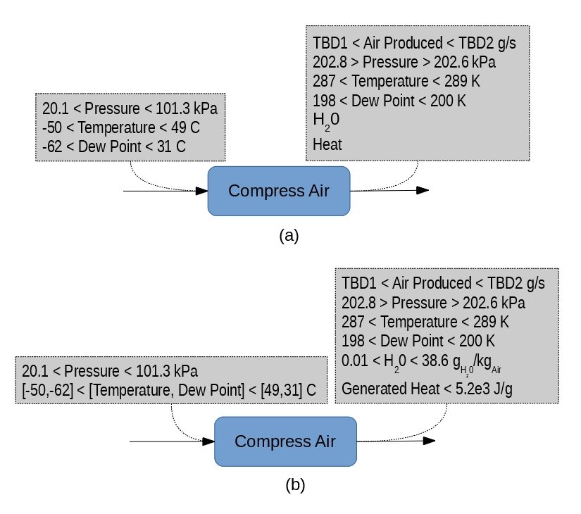
The reader should note that the original concept of the function provided no motivation for the important conclusion to vectorize the upstream parameters. When executed in isolation of a competent technical perspective, “functional analysis” will often miss crucial realities associated with physical reality17.
Horizontal Integration becomes more explicit in Figure 5 with identification of functions to dispose of the excess air, heat and water produced in the compression function. A consumption function is also shown in order to clearly distinguish the relationship between functional blocks and parameters.
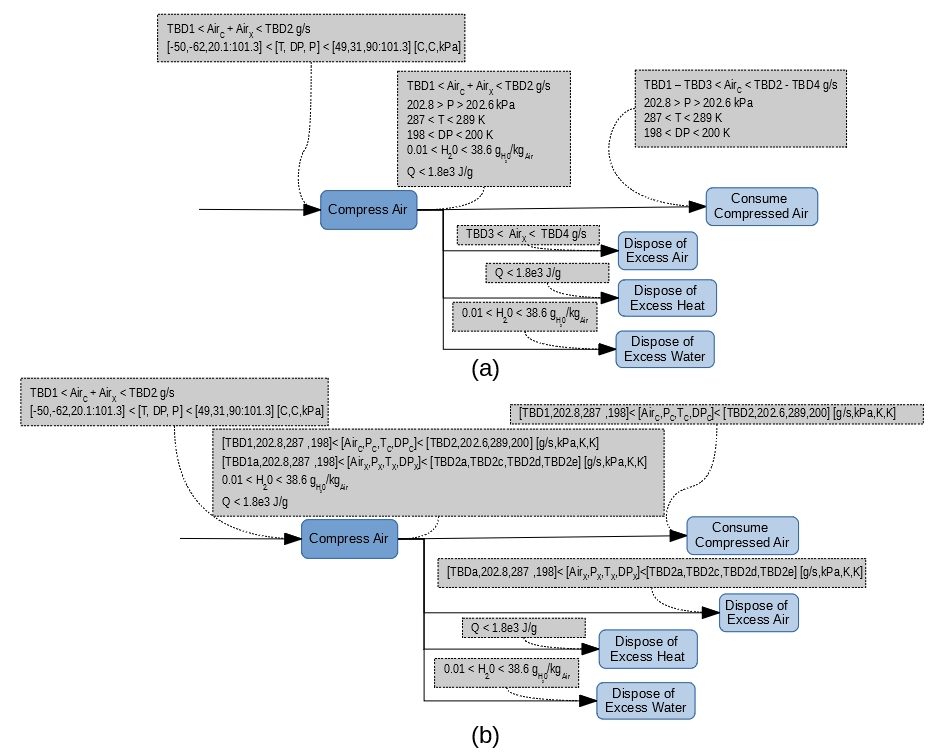
Note that not all parameters propagate downstream to all functional blocks. It will be recalled that the objective of the exercise is to identify the parameters that are controlled by each function. We’re not trying to build an executable model here.
Liberal use of TBD (“To Be Determined”) signifies that evaluation of parameters yet remains to be accomplished. In this case, their resolution is design dependent, and must be deferred until the relevant design decisions have been made18.
By breaking the “disposal” functions into individual entities, Figure 5(a) begins to flirt with concepts of decomposition. The approach shown in this figure subtly predicts that the developmental effort will distinguish between the three different species being dealt with (heat, air and water). From a pure “functional” perspective, it would have been acceptable to combine the three functions into a single “dispose of compression waste” function. The combination would then have easily admitted to the possibility that other kinds of waste will be discovered during development. No prejudice should be associated to either approach.
Aside
All three of the “disposal” functions are shown with their “upstream” parameters only, because they are “sinks” in the present context. Being “external” in the consideration of the subject function (“compress air”), we don’t care about how those parameters are managed. There will, of course, be at least one other context in which they’ll be treated with the necessary care.
Note that Figure 5(a) also redefines the bookkeeping of the air parameter. It divides the previously undifferentiated component into two distinct streams: one in support of downstream usage, and one admitting to the possibility of waste air. As shown, the figure is agnostic with respect to the state of any waste air. If the eventual design decision results in the presence of waste air, it may be necessary to separately distinguish a second air state in order to properly accommodate the waste “branch”. In that case, the flow rates of each branch would be combined with the state to form two vector-valued ranges, similar to Figure 5(b).
Figure 6 suggests two different approaches to further horizontal integration. Figure 6(a) suggests that the we have discovered (by analysis) or originated (by synthesis) a system-level intent to collect air outside the compression function; Figure 6(b) suggests the opposite. The distinction between the two approaches is made here to illustrate that the original definition of parameters and ranges for any given function might evolve along with an understanding of developmental intent at the context level. Here, the original (ambient) value ranges are moved to the newly-defined function, while an intermediate new set is interposed. Note, again, the liberal use (and enumeration) of “TBD”, to indicate work that cannot be accomplished without concurrent developmental decisions.
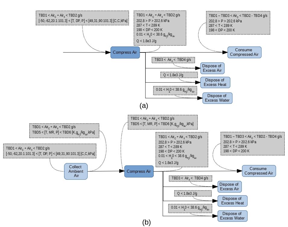
Note that Figure 6(a) and Figure 6(b) do not flow from the a/b branching of Figure 5. They represent an altogether separate branching topic.
There are significant differences of utility between Figures 6(a) and 6(b). Figure 6(a) would not, for example, be well-suited to the use of bleed air from some mid-stage port in a jet engine’s compressor. It lacks important points of integration between different parts of the Engineering staff and their respective components. In contrast, Figure 6(b) poorly supports the developmental situation in which the compressor is a stand-alone item: the performance of collection is uniquely associated with the subject compressor: the project might benefit if it were dealt with strictly in the context of decomposing the subject function.
Figure 6 exists here to emphasize the notion that an FFBD (and, therefore, Functional Analysis) is a developmental tool rather than merely an element of abstract documentation. It is of little use unless employed in the context of the overall developmental effort. These perspectives are sometimes lost by19 the general System Engineering community.
Figure 7 applies rudimentary conservation of material and energy to the evolving FFBD20. Note that the numbers do not explicitly sum to zero through the flow. This occurs because of their partitioning within the adiabatic function used to estimate values21.
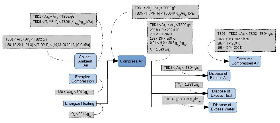
Application of conservation as shown implicitly assumes that any compression associated with collection of the air has little appreciable impact on the state of the collected air. This assumption is almost certainly too conservative in many cases. For example, the previously mentioned jet engine case would certainly not require any heating: the collected air would already be compressed to the point where cooling will always be required22. The same type of comments would almost certainly apply to the “Energize Compression” function that is identified on Figure 7.
Decomposition
As is true in many cases, this example’s decomposition is a synthesis (as opposed to an analysis): we postulate one or more sequences of subordinate functionality and the relationships between them for subsequent technical assessment. Figure 8 shows the raw material for decomposition which, by the nature of the exercise, include the interfacing functions and their vectors of parameters. As with many other figures in this exercise, Figure 8 is “as if on the whiteboard”. By itself, it is not an intrinsically important product; it is just a picture of the dots we need to connect during the decomposition process.
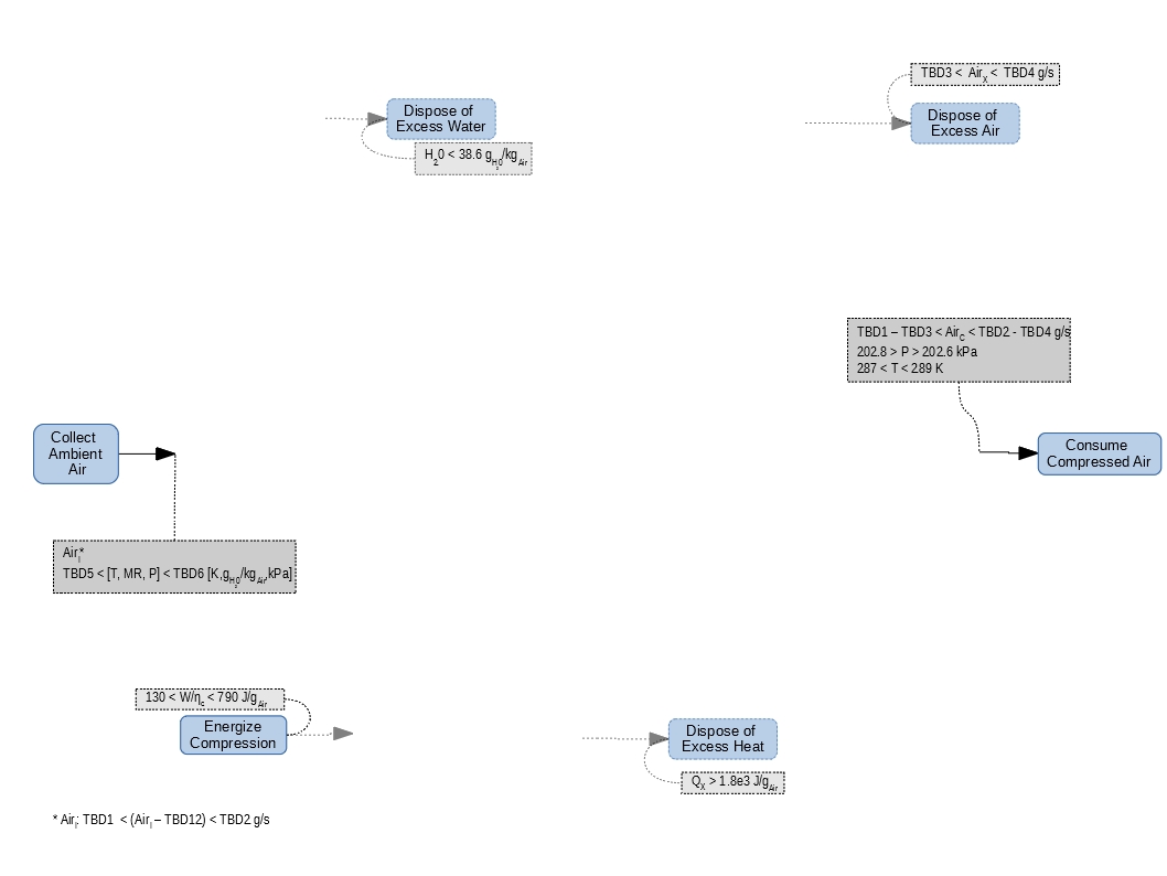
We use the parameters and their values to establish vertical linkage between the superior function (in this case, “compress air”) and the network of subordinate functions that effect the same change in the declared state parameters. This usage suggests (correctly) that decomposition is premature until a reasonable confidence in at least the identification of state parameters has been established. It is difficult to over-emphasize the importance of this point23.
Figures 9 – 11 show three different candidate decompositions for the subject function. In all three cases, these are “as if on the whiteboard”: none have yet been vetted by supporting analysis24. Some (possibly all) might be quickly discarded.
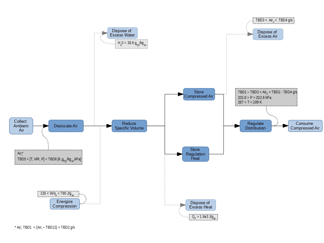

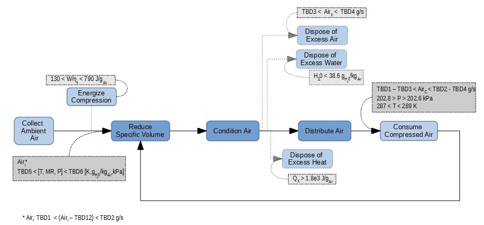
Note that, in addition to differences of function names in Figure 9, the grouping of the superior function’s state parameters is different within the three candidates. Furthermore, some of the state parameter values suggest that additional “vertical integration” of values may be required in the superior function. This is a reasonable outcome, since we’ll often want to trade off precision of interface specification against efficiency in a final design25.
Such “decoupling” of related developmental efforts allows them to proceed in parallel with occasional horizontal integration26. I will (again) observe that many of Measures of Performance have been left in their “extensive” formulation in order to support subsequent integration and optimization.
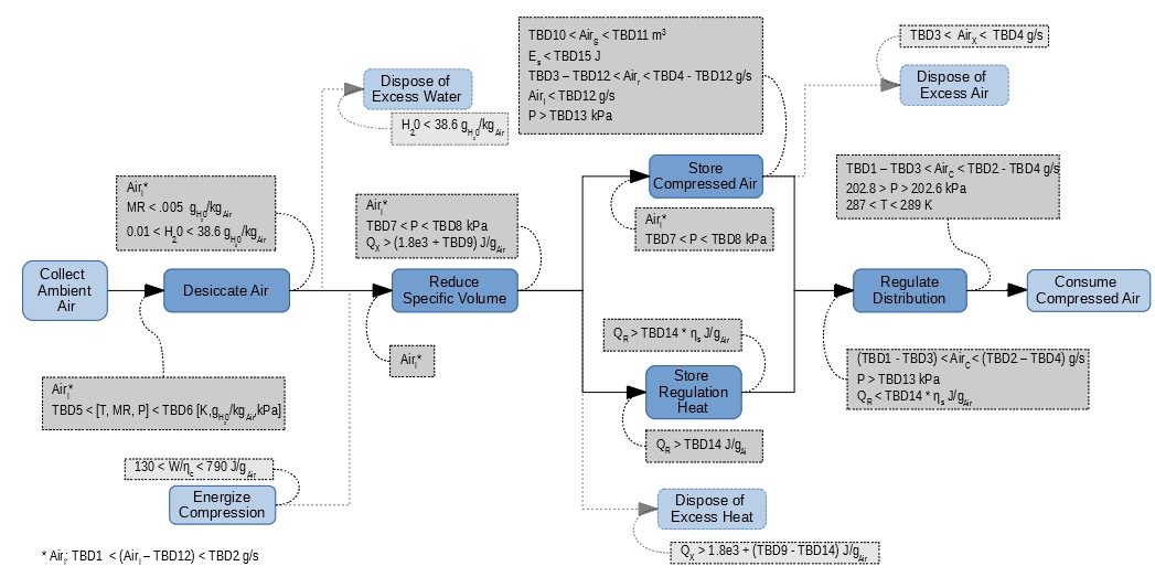
As an isolated point of exposition27, Figure 12 expands on Figure 9’s decomposition to identify additional state parameters and intermediate values. Tables 1 and 2 list the symbols and TBD’s; note that the listing of TBD’s correctly suggests that we’ve created an administrative control point for tasking and the potential for useful sensitivity analysis.
| Table 1: List of Symbols | |
| Symbol | Meaning |
| AirC | Compressed air rate to consumer (mass) |
| AirI | Compression inlet rate (mass) |
| Airr | Relief air rate (mass) |
| AirS | Air storage volume |
| AirX | Excess air rate (mass) |
| DP | Dew Point |
| Es | Stored Energy |
| MR | Moisture mass ratio (water vapor:air) |
| P | Pressure |
| QH | Supplied heat |
| QR | Heat stored for regulation |
| QX | Excess heat |
| T | Temperature |
| W | Work of compression |
| ηc | Efficiency of compression |
| Table 2: List of Parameters To Be Evaluated | |
| TBD# | Definition |
| 1 | Minimum air collection rate (mass) |
| 2 | Maximum air collection rate (mass) |
| 3 | Minimum excess air rate (mass) |
| 4 | Maximum excess air rate (mass) |
| 5 | Minimum air collection state vector |
| 6 | Maximum air collection state vector |
| 7 | Minimum compression pressure |
| 8 | Maximum compression pressure |
| 9 | Over-compression heat (delta above regulation pressure) |
| 10 | Minimum air storage volume |
| 11 | Maximum air storage volume |
| 12 | Leak rate from air storage |
| 13 | Minimum storage pressure (after leak-down) |
| 14 | Heat stored for regulation from over-compression |
| 15 | Maximum energy stored as compressed air (safety limit) |
Figure 12 is not “complete” in the sense of having identified all of the values. This is by intent: the decomposition is closely approaching28 the point at which a simulating model29 is more useful to the development process than is an FFBD. Such models support selection of a single decomposition from among multiple candidates30. Well-reasoned selection is critical to avoiding divergence between the various decompositions that exist in development of a complex product.
Figure 12 may also suffer from another conceptual error in System Engineering practice: most likely, there are existing functional models of the compression process that can (and should) be used in lieu of a unique effort. Decomposition should always be discontinued when a suitable functional model is discovered in the extant base of developmental knowledge. The only exception to that general rule is when existing technology is insufficient for the circumstances such that new functions (and/or sequences) are required in order to deal with them31.
Aside
It is quite common for System Engineers to plunge directly into decomposition. Counter-examples32 such as those shown in Figures 13 and 14 are a frequent result. Figure 13 suggests that, somehow, we can develop a design that will change exactly one parameter with exactly one function, and that they all change at the same time (as if independently of each other). As we have already seen, this can suggest that the laws of physics are irrelevant to System Engineering33. Figure 14 is as if the System Engineer recognized part of that problem, and was trying to fix it…but, in the end game, it cannot be fixed.
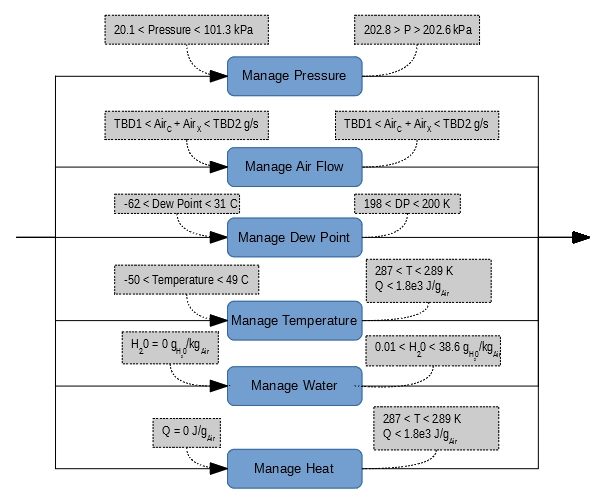
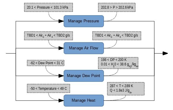
The philosophical error with Figures 13 and 14 is that they’re not functional decompositions: they’re decompositions of the parent function’s state vector into individual elements. They look like functions, but that isn’t actually the case. While there are Engineering problems for which state vector decomposition is equivalent to functional decomposition, it cannot be relied on as a standard approach.
Footnotes- That is, I’m going to do this pedantically in order to improve the exposure of cognitive processes.[↩]
- That is, there might not be a direct relationship to parameters “consumed” by subsequent blocks in the subject FFBD.[↩]
- In this case, other functions of the intended system.[↩]
- All of which is just a fancy way of saying “we put some numbers on it”.[↩]
- Or do some research if not already possessed of technically and operationally relevant skills.[↩]
- Pun intended.[↩]
- Sometimes called “studying”.[↩]
- When studying, it pays to be thorough, and you usually need to know more than you need to know in order to be sure you do know what you need to know. This drives management crazy, which is a wonderful side benefit.[↩]
- Through consultation with the relevant technical staff and potential End Users.[↩]
- We know these are important issues because we studied thoroughly…right?[↩]
- And our study of the natural environment tells us that isn’t always true.[↩]
- Many authorities on requirements insist that there be a 1:1 relationship between performance requirements and Measures of Performance.[↩]
- Which is, as a practical matter, pure nonsense.[↩]
- It is possible that additional benefit can be gained by an even more closely specified relationship between temperature and water vapor content, but I’ve made my philosophical point: such parameters are not necessarily scalars.[↩]
- Elements of a “functional interface”.[↩]
- Essentially telling the developer to disregard the obtuse potential for warm, moist air at very low pressure.[↩]
- As in most cases, the “studying” is more important than the tool.[↩]
- That statement suggests (correctly) that it would have been sufficient to conduct this exercise in a purely parametric manner – that is, without any numbers whatsoever. However, taking that approach in the context of teaching this material usually ends up in some nearby ditch.[↩]
- and on.[↩]
- Some of which was already considered in Figure 5.[↩]
- It should be recalled (again) that an FFBD is not an executable model…just a structural model in the ad hoc “function space”.[↩]
- In that situation, the “Compress Air” function would almost certainly be replaced or augmented with something like “Regulate Air” or “Condition Air”.[↩]
- No…really…IT IS DIFFICULT TO OVEREMPHASIZE THAT PREMATURE DECOMPOSITION IS A BAD IDEA.[↩]
- or by relevant expertise, for that matter![↩]
- Because that will tend to decouple the developmental efforts which (in turn) tends to avoid project development time and cost. It may, however, result in a system having one or more excessively large margins.[↩]
- By which I mean the lead-up to “Technical Reviews“, that being the purpose of such processes.[↩]
- That is, the candidates shown in Figures 10 and 11 will not be further developed in this example.[↩]
- or beyond![↩]
- By which I do not mean an “emulating model“.[↩]
- We call that a “trade study“.[↩]
- The precise meaning of “insufficient” depends on the context of the project at hand.[↩]
- By which I mean “done wrong”.[↩]
- Which is always a bad idea.[↩]